Semiconductors, EVs & Batteries
From wafer polishing to shipping battery packs
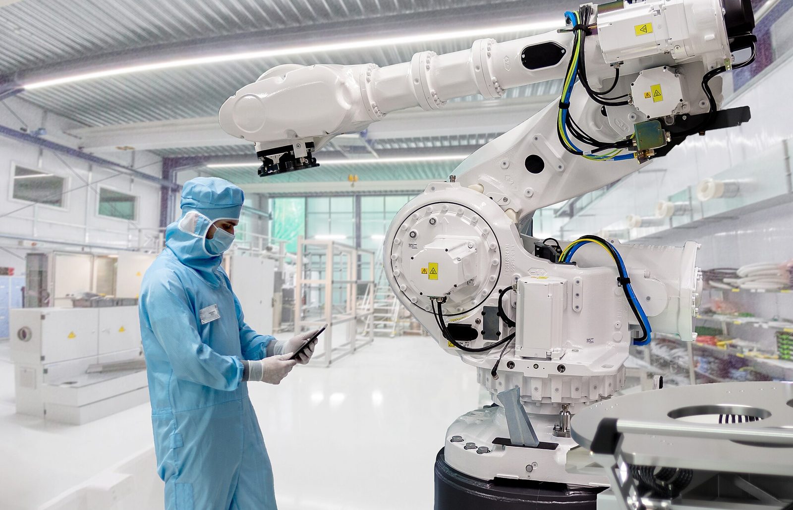
Semiconductors, EVs and batteries make chips, display panels, electronic modules, and battery cells and packs. A single particle or trace of residue on a surface can change how a device works or leave a defect on a screen.
- 75%
Fab yield loss from particle contamination
- 8-20%
LCD yield loss from poor cleaning
- 5-12%
Scrap rate in lithium-ion cell production
What is the semiconductor industry?
Semiconductor manufacturing builds chips by stacking fine circuits layer by layer on silicon wafers. As line widths have come down to nanometers, a single particle or trace metal ion left on the wafer surface now decides how a device behaves. Through wafering, patterning, thin film deposition, planarization and back-end encapsulation, the chemistry needed changes at each stage: polishing, cleaning, residue removal, vacuum equipment lubrication and rust protection for shipping.
On a semiconductor line, problems show up in yield. Yield is eroded not by visible defects but by small amounts of contamination and residue building up, so tracing back to the cause is difficult. That is why chemicals must be checked and recorded lot by lot, not only for performance but also for purity, residue and changes in raw materials and refining conditions. Semiconductors are not a one-delivery business; line conditions and validation data are aligned together over several years.
- 01
Wafer slicing, lapping and polishing
High-purity ingots are sliced thin, then lapped and polished to set flatness and surface purity. Trace process chemicals left on the surface show up as defects later. Choose process fluids and cleaners by processing performance and metal ion and particle content.
- 02
Photolithography with resist coating, exposure and development
Photoresist is applied and exposed, then developer selectively removes it to form patterns. Contaminated or degraded chemicals directly cause pattern defects. Choose chemicals by resolution and ultra-high-purity grade.
- 03
Dry plasma and wet etching
Exposed films are removed with plasma or wet solutions to form circuit patterns. Contaminated etchant lowers repeatability, causing over-etch or undercut. Choose chemicals by etch performance and selectivity to underlying films.
- 04
Post-etch cleaning
Polymer residue and leftover resist from etching are removed on a separate line. Weak cleaning lets residue reattach, and aggressive chemistry corrodes metal layers. Choose a cleaning solution by residue removal and metal layer damage.
- 05
PVD and CVD thin film deposition
Metal and insulating films are deposited by physical or chemical vapor deposition. Uneven thickness or particles cause rework. Choose precursors and chamber cleaners by film quality, purity grade and byproduct handling.
- 06
Chemical mechanical polishing (CMP)
Slurry and pads remove material by combined chemical and mechanical action to planarize multilayer interconnects. Agglomerated slurry particles or lagging pad conditioning cause scratches and dishing. Choose slurry by removal rate and particle size distribution.
- 07
Post-CMP cleaning
Slurry particles, metal ions and organics left right after polishing are removed by wet and dry methods. Reattached particles or leftover ions lower multilayer interconnect yield. Choose cleaning solutions by removal performance and redeposition control.
- 08
Vacuum chamber and pump lubrication
Bearings and valves in etch and deposition tools are lubricated and pumps filled with dedicated oil to hold vacuum. Volatile components from lubricants lower the vacuum. Choose oil types by lubrication performance, outgassing and heat resistance.
- 09
Diffusion and anneal heat treatment
Heat diffuses dopants or drives crystallization. Temperature variation across the wafer shows as spread in device characteristics. Choose heat transfer oils and coolants by thermal performance and temperature range.
- 10
Back-end packaging
In the back end, chips are attached to substrates, wire bonded, encapsulated in epoxy, singulated and tested. Moisture absorbed before molding expands in reflow, causing delamination. Choose products by bond strength and humidity control in storage before molding.
What is the electronics and display industry?
The electronics and display industry makes the screen panels and electronic modules that go into smartphones, TVs and vehicle instrument clusters. Thin film transistors and emissive layers are stacked very thinly on glass or polyimide substrates, so even a small organic mark left on the surface shows up as a defect on the screen. Because substrates, metal thin films, organic materials and circuit boards are handled together, requirements change with every layer: precision cleaning, residue removal, encapsulation and bonding, contact protection and equipment lubrication.
The risks in this industry are moisture, oxygen and fine contamination escaping from equipment. Organic emissive layers lose their emission properties on contact with moisture, and volatile components from equipment lubrication lower deposited film quality batch by batch. So purity, particles, volatile components and the long-term reliability of coating and bonding materials must be weighed alongside performance data. In electronics and displays, a decision to change one material is made over several years, so the validation schedule should be planned from the start.

- 01
Substrate cleaning
Particles, organics and metal ions are removed from glass or polyimide substrates to prepare the base for patterning. Fine particles left behind unsettle yield in all later steps. Choose cleaners by cleaning power, substrate fit and recontamination.
- 02
Photoresist coating, exposure and development
Photoresist is applied to the substrate, exposed and developed to form circuit patterns. Resist thickness variation causes broken patterns or uneven development. Choose chemicals by resolution, electronic-grade purity and stability in storage.
- 03
Etching and resist stripping
Etchant removes unwanted thin films, then stripper removes remaining resist. Unstable selectivity causes undercut, and incomplete stripping leaves residual film. Choose chemicals by removal power, selectivity and bath life.
- 04
Thin film deposition for TFT formation
Oxide, metal and semiconductor layers are deposited in sequence to form thin film transistors. Particles in the chamber unsettle device characteristics for that batch. Choose chamber cleaners and maintenance fluids by cleaning power and the effect of residue on the next film.
- 05
OLED organic emissive layer deposition
Fine metal masks are used in a vacuum chamber to deposit emissive, hole and electron layers at the molecular level. Organics on masks mean scrapping a whole batch. Choose cleaners by removal power, residue-free performance and mask material compatibility.
- 06
Moisture-barrier thin film encapsulation (TFE)
Inorganic and organic films are stacked alternately to protect organic layers from moisture and oxygen. One pinhole of moisture breaks down emission there. Choose encapsulants by barrier performance and outgassing data.
- 07
Driver IC packaging
Display driver ICs are packaged by die attach, wire bonding, molding and underfill, then attached to the panel. Voids left in underfill are where cracks start. Choose bonding materials by bond strength, flow and cure conditions.
- 08
Conformal coating and thermal management
A protective coating is applied over module boards and component surfaces, and thermal materials are applied to hot spots. Bubbles or cracks in the coating lower both insulation and heat dissipation. Choose materials by thermal conductivity, insulation resistance and flame rating.
- 09
Connector and FPC contact assembly
Flexible circuit boards, connectors and frames are attached to the panel and contacts are lubricated. Fretting and oxidation raise contact resistance slowly. Choose contact protectants by lubrication, oxidation control and plating fit.
- 10
Equipment cleaning and precision lubrication
Deposition and etch chambers, transfer robots and vacuum systems are cleaned regularly, and bearings and linear guides are lubricated. Volatiles that contaminate chambers unsettle line yield. Choose lubricants by service life, load conditions and outgassing data.
- 11
Final inspection and packing
Optical, electrical and reliability performance is checked, then panels are packed and shipped. In transfer and packing, reflective films can be damaged or devices harmed by static. Choose packaging materials by cushioning and antistatic grade.
What is the EV and battery industry?
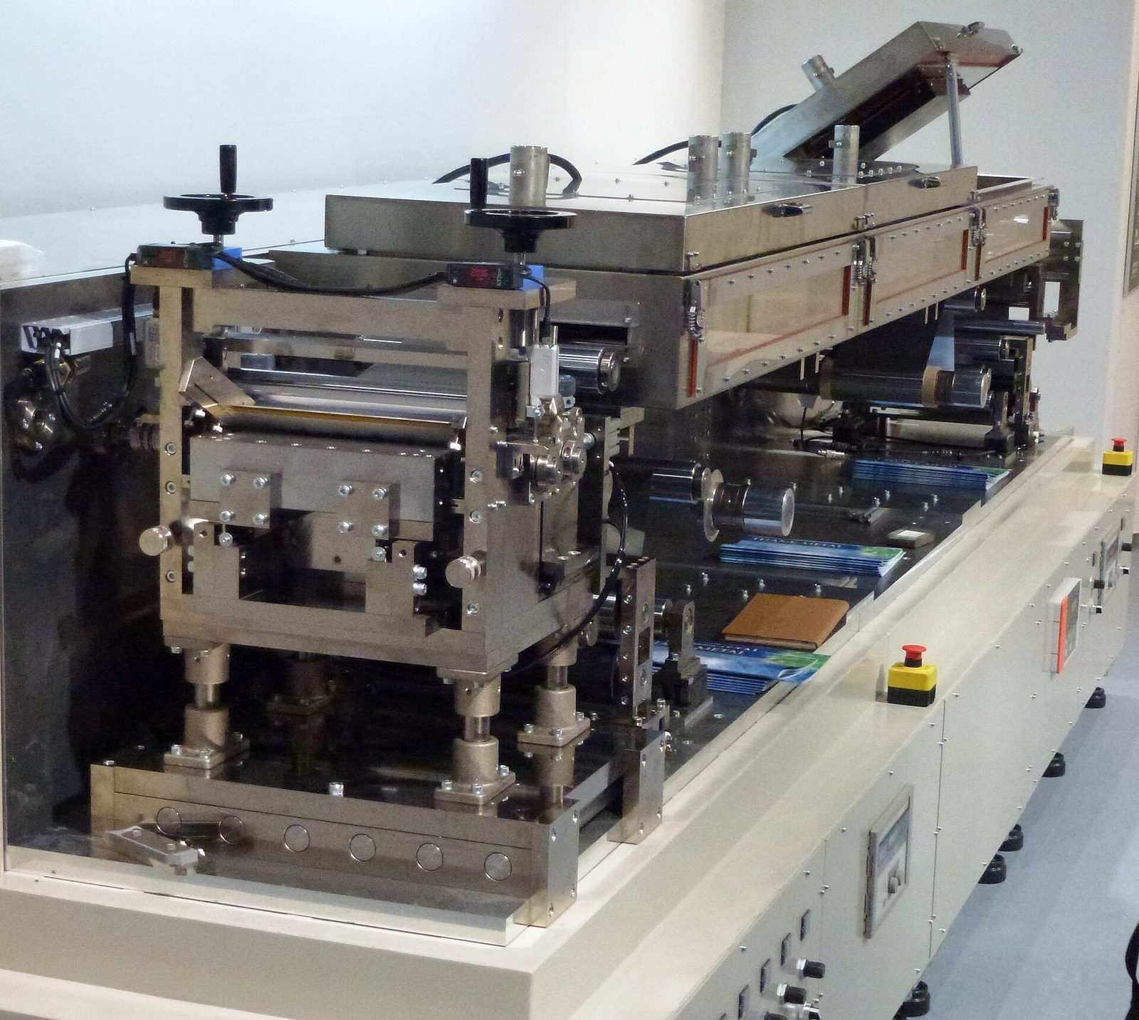
The battery industry makes the cells, modules and packs that go into electric vehicles and energy storage systems. From making electrodes and assembling cells to filling electrolyte and bundling packs, processes must run while keeping the inside, where electrochemical reactions take place, sealed off from the outside environment. Because aluminum foil, copper foil, active materials, separators and casing metals are handled together, rolling and cutting lubrication, cleaning that leaves no residue, insulation and sealing, and rust protection are each required under different conditions at each stage.
The biggest risk in batteries is invisible contamination. Moisture, trace ionic impurities and residue transferred from equipment change cell life and safety. So chemicals that touch the cell must come with evidence on moisture content, ion concentration, material compatibility and residue composition for every delivered lot, alongside performance data. In batteries, chemistry is a material that leaves traces inside the cell, so not only performance but also those traces must be checked together with the cell maker.
- 01
Slurry mixing
Cathode and anode active materials are mixed with conductive additives, binder and solvent into a uniform slurry. Agglomerated particles or bubbles carry viscosity variation into coating thickness variation. Choose additives by dispersing, defoaming and batch-to-batch repeatability.
- 02
Electrode coating and drying
Slurry is coated onto aluminum foil for cathodes and copper foil for anodes, then solvent is driven off at high temperature. Drying too fast pushes binder to the surface, cracking the electrode or delaminating it from the current collector. Choose primers and cleaners by adhesion, moisture content and residue.
- 03
Calendering
Dried electrodes are pressed by roll press to bring density and thickness to specification. Active material sticking to the roll surface leaves repeated scratch marks on the electrode. Choose rolling oils and cleaners by friction reduction, electrolyte compatibility and residue.
- 04
Slitting and notching
Calendered electrodes are cut to width and tab shapes are cut and formed. Burrs left on cut edges become starting points for internal shorts. Choose cutting fluids by cut edge quality, tool life and antistatic performance.
- 05
Stacking and winding
Cathode, separator and anode are stacked or wound in turn into the electrode assembly. Misalignment beyond the separator margin leads to internal shorts. Choose equipment fluids by lubrication, low residue and static behavior.
- 06
Tab welding and case insertion
Current collector tabs are welded, and the assembly is inserted into a steel or aluminum casing and sealed. Incomplete cleaning and drying after casing forming seals moisture and oil inside. Choose forming and rust preventive oils by formability, rust protection and removal by cleaning.
- 07
Electrolyte filling and sealing
Organic electrolyte is filled into the casing and sealed in a dry room kept at low dew point. Unstable fill volume or incomplete sealing lets moisture in and shortens cell life. Choose cleaners and sealants by residue, sealing reliability and moisture control.
- 08
Formation, aging and degassing
Cells are charged and discharged repeatedly at high temperature and voltage to form the initial film, aged, then degassed. Cells not fully degassed move on holding gas and later show swelling. Choose formation equipment fluids by cooling performance, insulation and thermal stability.
- 09
Module assembly
Dozens of finished cells are connected with busbars and fixed in an insulating case. Crushed or shifted insulating members cause shorts between cells and busbars. Choose adhesives and sealants by bond strength, sealing and insulation.
- 10
Pack assembly and protection
Modules are fixed in the pack casing, controls, wiring and cooling are integrated, and waterproofing and flame protection are applied. Galvanic corrosion appears where aluminum housings meet steel brackets. Choose a sealant by waterproofing, cure conditions and flame standards.
- 11
Final inspection, packing and transport protection
Finished packs are verified for performance and safety, then packed for long transport. Vibration and humidity changes in transit start corrosion at fastening points and exposed metal. Choose rust preventives and packaging by protection period, protection strength and packing method.
Regulation and certification
SEMI standards
International standards for semiconductor equipment and materials published by SEMI. Process chemicals are graded under the SEMI C series, which sets their purity and metal impurity limits.
ISO 14644
The international standard series for cleanroom cleanliness classes and their control. Lubricants and cleaners used inside are checked for particles against the class and for volatiles against the molecular contamination part, ISO 14644-8.
UL 94
The UL standard that tests the flammability of plastic materials and assigns ratings such as V-0 and HB. Potting compounds, adhesives and insulating materials in battery packs are checked for the required rating.
Chemicals Control Act (Korea)
Korean law governing facilities, business permits and accident preparedness for hazardous chemicals. Etching and cleaning chemicals classed as hazardous must follow its handling and facility requirements.
FAQ
Back-end processes still catch particles after cleaning. Where do we look first?
The cause is more often in rinsing and drying than in the cleaning solution itself. Detached particles can reattach in the bath or stay on the surface while drying is delayed.
Rinse water quality and drying delay remain even when the cleaning solution changes, so in many cases only the solution is swapped and the same values repeat. On the other hand, raising cleaning power can damage underlying metal layers and cause different problems in interconnects. On lines with a long wait between cleaning and the next process, it is better to address that stage first.
Can we swap the tool maker's specified vacuum pump oil for another product?
Sometimes, but check the equipment warranty conditions first. In some cases the warranty is not kept outside the specified oil type, and identifying the cause takes longer when a problem occurs.
If vacuum drops while running off-spec oil, it takes time to tell whether the pump or the oil is the cause, and the tool may be down in the meantime. So even when switching, many start with equipment out of warranty or spare pumps to build outgassing and high-temperature durability data.
Scratches increased after CMP. Do we need to change the slurry?
It may be the slurry, but it is better to check pad conditioning and the supply piping as well. Slurry particles agglomerating in piping or tanks and arriving as large lumps often show up as scratches.
One way to check is to look at scratch length and direction. Long scratches in a consistent direction point first to large particle intake; short, scattered ones point first to pad condition and pressure settings.
Does slightly changing a cleaning solution or slurry mean validating again?
Often, yes. Ingredient registration and residue-free validation are tied to composition, so even a trace ingredient change means preparing new data.
Revalidation needs both test volume and line availability, so even with all data ready, a product can miss a quarter if no evaluation window is available. Trace ingredient changes can also come quietly from the supplier's raw material situation, so setting a prior notice condition for composition changes at the contract stage keeps things simpler later.
After cleaning, stains remain only near the substrate edges. Why?
On large substrates, dwell time and rinse conditions often differ by position. At the edges, solution drains first and dries faster, so residue can remain as marks.
The point to check is whether the stain always appears in the same place. If it repeats in the same place, look first at nozzle layout or transfer angle; if the location changes each time, look first at cleaning solution condition and rinse water quality.
Residual film remains after stripping. Will a stronger stripper fix it?
Sometimes, but damage to underlying layers can increase as well. If residual film stays only in certain areas, uneven temperature or flow is a more likely cause than the strength of the solution.
Raising stripping power brings in underlying layer damage and bath life, so even when residual film decreases, waste burden and change frequency can increase. If residual film always remains in the same place, the problem likely starts with flow and temperature distribution rather than the chemical, and in that case it often repeats in the same place even with a different solution.
How does electronic-grade purity really differ from general industrial grade?
The items managed and the units differ. Analyzing metal ions and particles to much lower levels and keeping a certificate for every lot is where it departs from industrial grade.
Even with the same grade label, different measurement items and detection limits change what the values mean, and using industrial-grade data as is leaves no basis to trace back when spread appears on the line. Higher purity grades also raise unit price and lead time, so some set the required grade separately for each stage.
Does a material change always get side-by-side evaluation with the current one?
Often, yes. Panel materials directly affect device characteristics and lifetime, so short tests are not enough to judge, and comparing with the current material on the same line is the usual approach.
If line conditions change during evaluation, earlier results become hard to reuse and the evaluation sometimes starts over. Panel materials are often tied to exclusive supply arrangements, so even after passing parallel evaluation, volume does not move over at once but grows in steps starting from some lines.
Will new rolling oil stop recurring electrode scratches after calendering?
It could be the rolling oil, but it is often caused by active material sticking to the roll surface. In that case, marks repeat in the same place even with a different fluid, and if they repeat at regular intervals across the width or disappear only right after the roll is wiped, the roll is the more likely cause.
If roll contamination is the cause, cleaning intervals and release conditions are addressed first, and trying to cover it with more release agent can also increase residue transferred to the electrode. Looking at the friction properties and residue of the rolling oil is not too late after the roll surface condition is sorted out.
We fear equipment fluids may transfer onto electrodes. How far must we check?
Even trace transfer can change cell characteristics, so in calendering and assembly, compatibility data for electrolyte and active materials is often reviewed. Performance data alone usually does not finish the review.
Where there is direct contact, residue composition data is normally needed; where cleaning sits in between, confirming residue after cleaning is the usual scope. Adding another cleaning step, however, brings new moisture and cleaner residue, so choosing a fluid that transfers less often makes management simpler than covering it with cleaning.
How should dry room chemicals be chosen differently from a regular line?
First, whether they bring moisture in themselves. In a space kept at low dew point, hygroscopic ingredients can make the dew point fluctuate from the material side rather than the equipment, and in that case no amount of equipment inspection finds the cause.
Package size and handling after opening also matter. For materials used in small portions, time left open can be the actual moisture entry route, and if the staging area before entry is outside the dry room, materials sometimes come in already holding moisture.
We hear cell maker vendor registration is long. What is the sequence?
Data review usually comes first. Only after ion and moisture certificates and compatibility data for electrolyte and active materials are checked does it move on to trial on the line. Leading with performance data alone sometimes stops at this stage.
Next come small-volume trial application and field test history, then internal approval with those results attached, after which volume increases. The closer a stage is to cell performance, such as electrolyte filling or formation, the longer the validation period in between, so the adoption schedule is often set by the length of the process rather than by product performance.