The chemistry that runs the plant behind the line
Water treatment, heat transfer fluids, release agents and process aids, heat treatment and metallurgy. The fluids and chemicals that keep the plant running.
What process and utility chemicals are
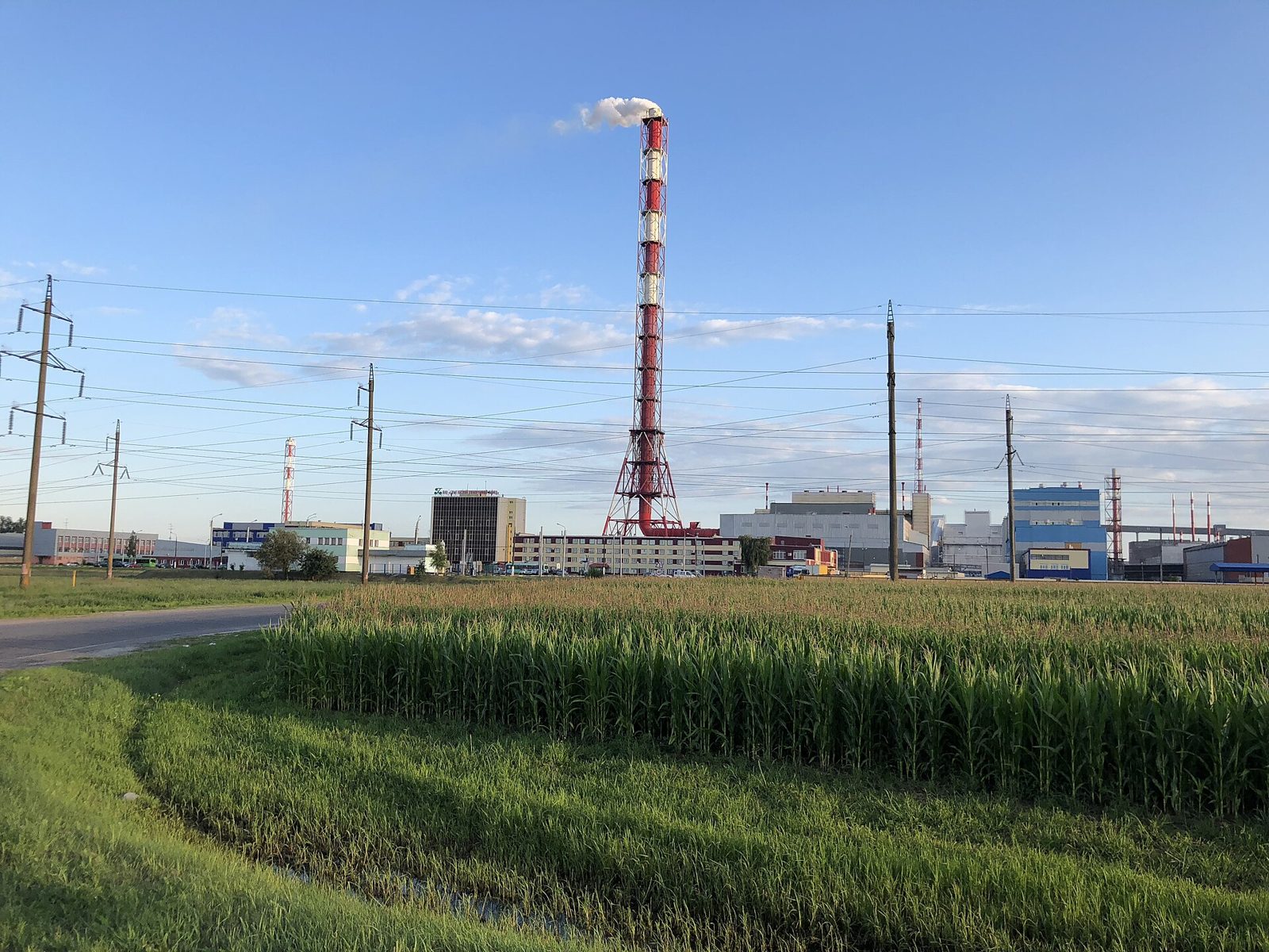
Process and utility chemicals are chemicals used to run processes and equipment without becoming part of the product. They divide into utilities shared by the whole plant, such as water and heat, and items inside the process that touch the product directly, such as molds and heat treatment baths. Some chemicals never remain in the finished product, yet the line stops without them: the water circulating through boilers and cooling towers, the release agent that frees a product from its mold, the quenchant in a heat treatment bath. When something goes wrong, it rarely shows on the product drawing and often surfaces only after scale blocks a pipe or discharge water exceeds its limit.
The categories run from utilities into the process. Water and waste treatment, which handles incoming and outgoing water, comes first, followed by heat transfer and cooling, where water and fluids carry heat. Next are release and process aids, which handle the face where mold and product meet, and thermal and metallurgical, which changes the structure through heating and cooling. Detection and utilities, which finds leak points, and the process umbrella, which gathers system changeover work, come last.
Two things are checked first when choosing. One is whether the chemical touches the equipment or the product. If it touches equipment, the system materials and operating conditions are the reference. If it touches the product, residues and the downstream process are the reference. The other is where it goes after use. At a site with set discharge volumes and disposal methods, the treatment load matters as much as performance.
- 469
Process conditions checked before a recommendation
- 50%
Sludge handling share of wastewater plant running cost
Water & Waste Treatment
Gathers and settles impurities in incoming and outgoing water and also protects the systems the water passes through. Coagulation removes solids, pH adjustment balances the water, and dewatering takes the water out of sludge. 9 industries call for this category: Thermal & Combined-cycle Power, Semiconductors, Nuclear, Non-ferrous Metals, Aerospace and more.
- Coagulant
- Flocculant
- RO and boiler water treatment
- pH and alkalinity control chemicals
- Sludge dewatering aid
- Biocide
Heat Transfer & Cooling
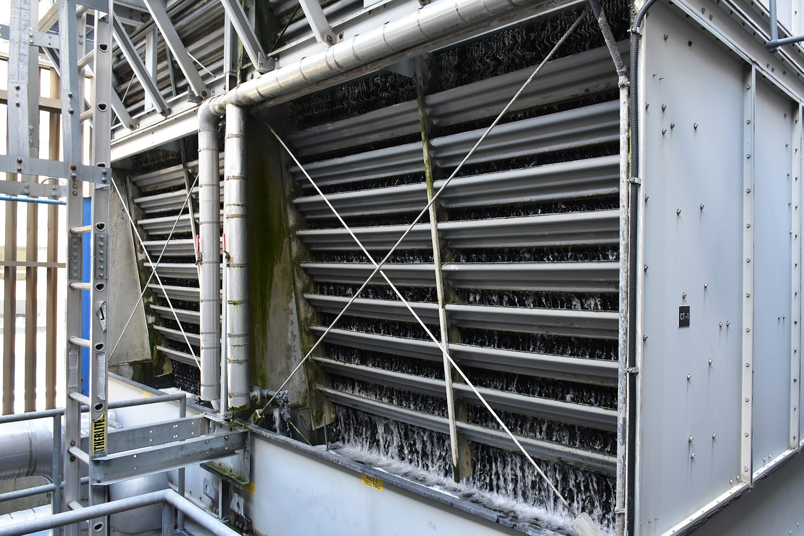
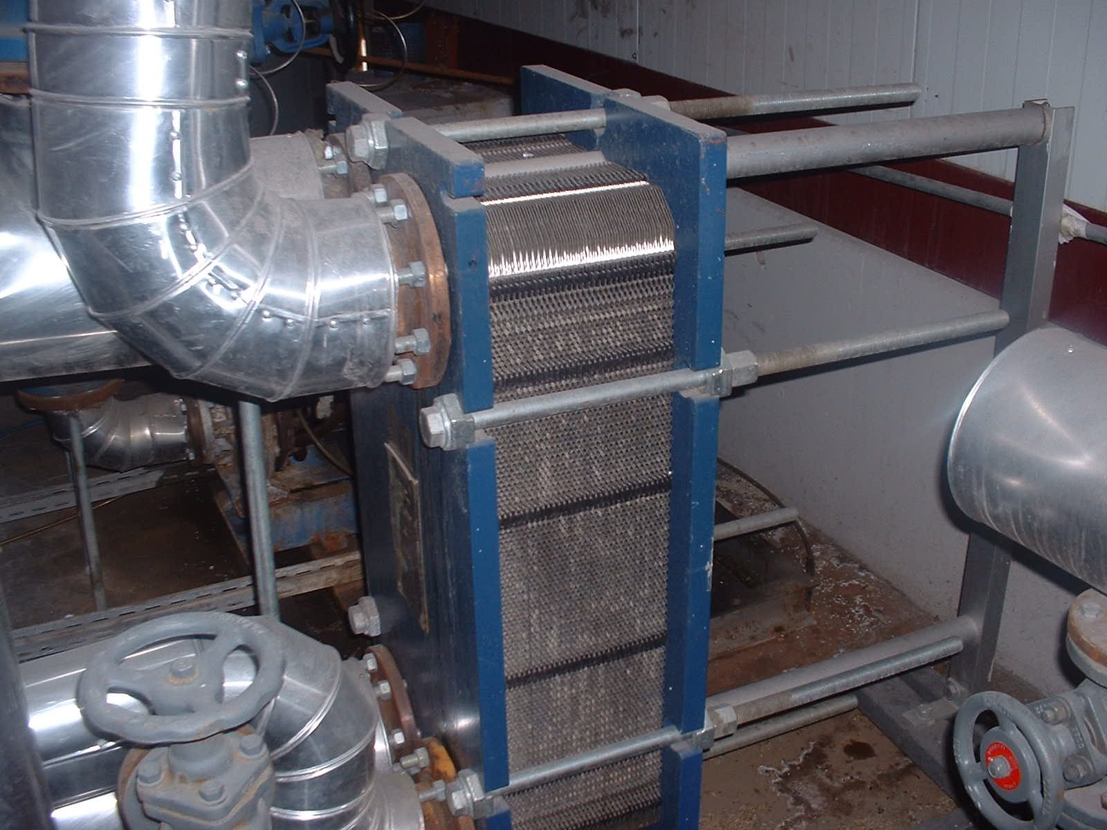
Manages the fluids that carry heat and the piping they flow through, matched to the temperature range. Thermal oils handle high temperatures, glycols handle temperatures below freezing, and in closed loops pipe corrosion comes first. 13 industries call for this category: Data Centers, Food & Beverage, Non-ferrous Metals, Casting & Forging, Thermal & Combined-cycle Power and more.
- Heat transfer fluid
- Coolant and antifreeze
- Closed-loop corrosion inhibitor
- Cooling water treatment
Release & Process Aids
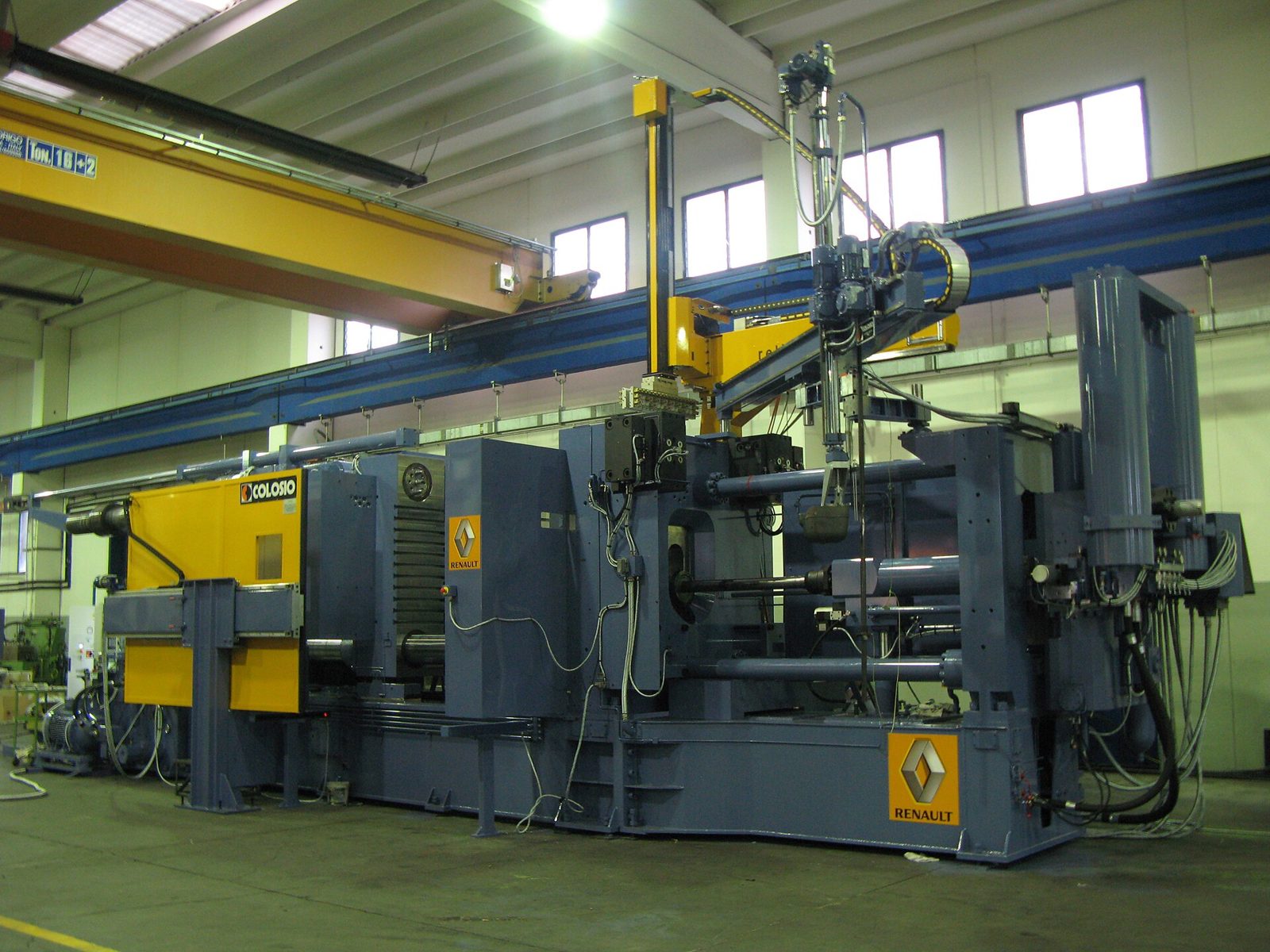
Decides release, surface condition and suitability for downstream processes at the face where mold and product meet. Die casting, rubber molding and concrete differ in temperature and material, so each uses a different release agent. 12 industries call for this category: Casting & Forging, Glass & Ceramics, Construction Equipment, Nuclear, Semiconductors and more.
- Die-casting release agent
- Press and concrete release agent
- Rubber and plastic mold release agent
- Process oil
- Defoamer
Thermal & Metallurgical
Balances reaching hardness against limiting distortion and surface oxidation during heating and cooling. Cooling fast makes parts hard but can warp or crack them, while cooling slowly may not reach the target hardness. 3 industries call for this category: Casting & Forging, Automotive Parts, Machinery & Precision Machining.
- Quenching oil
- Polymer quenchant
- Carburizing stop-off coating
- Nitriding stop-off coating
- Anti-scale coating
- Heat-treating salt
Detection & Utilities
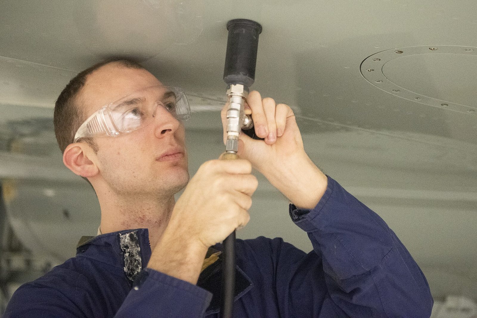
Fluids that find leak points that are hard to see, during testing or in operation. One method shows leaks with bubbles; the other mixes a dye into the system and finds leaks under ultraviolet light. 5 industries call for this category: EV & Batteries, Robotics & Logistics Automation, Construction Equipment, Wind, Solar.
- Leak detector
- Fluorescent leak detection dye
- Dye penetrant
- Magnetic particle testing media
- Ultrasonic couplant
Process Umbrella
Empties and prepares a system before a fluid is changed or restarted. If old fluid and sludge are not flushed out, the new fluid circulates contaminated from the start. 2 industries call for this category: Pharma & Medical Devices, Agricultural & Forestry Machinery.
- Flushing oil
- Lubrication system cleaner
- Varnish remover
- Running-in oil
FAQ
How high can we push cycles of concentration on a cooling tower?
Cycles of concentration describe how many times more concentrated the recirculating water is than the makeup, usually calculated from the ratio of conductivity or chloride. Evaporation leaves the dissolved salts behind, so every cut in blowdown raises the cycles. Makeup and chemical consumption drop, but calcium, alkalinity and silica concentrate in the loop as well, although alkalinity often rises less than chloride because acid feed consumes it and calcium carbonate precipitation removes it. CO2 stripping in the tower raises pH but does not by itself reduce total alkalinity.
The ceiling is set by whichever makeup constituent hits its limit first. Hard, alkaline water runs into calcium carbonate scale, high-silica water into silica deposition, and soft water with high chloride into corrosion. The limits of the inhibitor program and the discharge permit can also set the ceiling. Copying another site's cycles without a makeup analysis has no technical basis.
Blowdown is roughly evaporation divided by cycles minus one. Going from 2 to 4 cycles cuts blowdown to a third and makeup by a third, but going from 6 to 8 trims makeup by only about 5 percent while the scaling margin keeps shrinking. Past a certain point the cost of a fouled heat exchanger outweighs the water saved.
In operation, compare the calcium ratio separately against the chloride, silica or conductivity ratio. A calcium ratio clearly lower than the reference means calcium is precipitating somewhere in the system. Chlorine or bromine biocides and hydrochloric acid feed add chloride, so on those programs the chloride ratio overstates true cycles.
What can the Langelier and Ryznar indices tell us about scale and corrosion?
The Langelier Saturation Index (LSI) is actual pH minus the calcium carbonate saturation pH. Positive means a tendency to deposit calcium carbonate, negative a tendency to dissolve it. The Ryznar Stability Index (RSI) is twice the saturation pH minus actual pH; as a rough reading, below 6 leans toward scaling and above 7 toward corrosion.
Both are thermodynamic tendencies for calcium carbonate only. They say nothing about how fast or how much scale will form, they ignore silica, calcium phosphate and calcium sulfate, and they do not predict corrosion rate, which depends on chloride and sulfate, dissolved oxygen, temperature, velocity, deposits, microbial activity and metallurgy. A treated system with scale inhibitor is deliberately run supersaturated, so a positive LSI on its own is not a fault.
A common mistake is calculating at basin temperature. Saturation pH falls as temperature rises, so the meaningful value is at the hottest wetted surface, typically the heat exchanger tube wall. An index calculated at basin temperature understates the scaling risk.
Use the indices to set the direction of the treatment program, and confirm the result with corrosion coupons, a monitoring heat exchanger and the trend in exchanger approach temperature.
How are oxidizing and non-oxidizing biocides split for cooling tower Legionella?
The water management plan comes before the chemistry. ASHRAE 188 requires a water management program built on a hazard analysis, with control locations and limits, monitoring, corrective action and verification; the UK HSE ACOP L8 and HSG274 require a risk assessment and a written control scheme. Real risk tends to sit in dead legs, damaged drift eliminators, biofilm and restarts after long shutdowns.
Oxidizers such as chlorine, bromine and chlorine dioxide act quickly and form the baseline program with a continuous residual. Chlorine loses effectiveness as pH rises because less of it is present as hypochlorous acid, so towers run on the alkaline side often consider bromine or chlorine dioxide. Oxidizers also consume azole copper inhibitors and react with some scale inhibitors, so the whole program has to be balanced together.
Non-oxidizers such as isothiazolinones, glutaraldehyde and DBNPA are slug-dosed periodically to penetrate biofilm and catch organisms that tolerate the oxidizer. Each needs its own contact time and has its own pH stability; DBNPA, for example, hydrolyzes quickly at high pH. Holding blowdown for a period after dosing may be needed to secure contact time.
Legionella cultures take days, so day-to-day control runs on surrogates such as oxidizer residual and heterotrophic plate counts, with periodic Legionella sampling to verify the program. HSE expects cooling towers to be tested for Legionella at least quarterly; ASHRAE 188 treats testing as one validation option rather than a requirement. Biocides must be registered for that use in the market where they are applied.
What do we measure on closed-loop glycol to judge condition and change timing?
First, concentration. Check freeze point with a refractometer and use the correct scale for ethylene or propylene glycol. Too dilute, and you lose not only freeze protection but inhibitor strength. Glycol suppliers generally treat about 25 percent as the floor below which glycol feeds bacteria and inhibitor levels become inadequate. Too strong, and specific heat falls while viscosity rises, so heat transfer and pumping efficiency both suffer.
Second, how much inhibitor is left. Glycol oxidizes at temperature in the presence of oxygen into organic acids, chiefly glycolic acid from ethylene glycol and lactic acid from propylene glycol, along with formic and other acids. These acids consume reserve alkalinity and inhibitor. pH is a late indicator; the trend in reserve alkalinity and key inhibitor components gives earlier warning.
Third, evidence of corrosion already under way. Rising dissolved iron, copper or aluminum means the inhibitor is no longer protecting that metal, while odor, turbidity and sludge point to microbial contamination or degradation.
The usual mistakes are topping up with tap water and mixing coolants built on different inhibitor chemistries. Hard water forms scale and precipitates, and incompatible inhibitor packages can drop out of solution. Top up with the same product or one confirmed compatible, and dilute with deionized water or water that meets the supplier's chloride, sulfate and hardness limits; softening removes hardness but leaves chloride and sulfate.
Why does an inhibited closed loop keep corroding and making sludge?
Start by checking that the loop really is closed. A steady leak or a weeping relief valve brings in fresh makeup, and every liter carries oxygen and hardness while diluting the inhibitor. If there is no makeup meter, the rate at which inhibitor concentration falls gives a back-calculated estimate of makeup. This only holds if the inhibitor is not also being consumed, so check that conductivity or an inert tracer falls with it.
In nitrite-based programs, nitrifying bacteria can oxidize nitrite to nitrate, and the residual can collapse within a short period. If nitrite drops while conductivity holds steady and nitrate rises, suspect microbial activity before a leak or underdosing, and confirm with a bacteria count.
Metallurgy is another cause. A high-pH program tuned for steel can attack aluminum heat exchangers, and copper alloys need a dedicated inhibitor such as an azole. Dissimilar metals in contact can corrode galvanically, and dissolved copper can plate out on steel or aluminum and pit it even without direct contact, so list every wetted material before setting the program.
A loop that was never cleaned and passivated at first fill can shed mill scale, weld debris and cutting oil for years. In that case, adding more inhibitor helps less than a cleaning plan guided by a side-stream filter and corrosion coupons.
How do we tell what is degrading a heat transfer fluid, and when to replace it?
There are two routes. Oxidation happens where hot fluid meets air, usually in the expansion tank, and shows up as rising acid number and viscosity, sludge and varnish. Thermal cracking happens when the film temperature at the heater tube wall exceeds the fluid's rated maximum film temperature, breaking molecules into low boilers, while recombining fragments form high boilers.
Low boilers pull the flash point down and cause pump cavitation and heavier venting at the expansion tank. High boilers raise viscosity and lay down carbon, which cuts heat transfer, makes the tube wall run hotter and accelerates cracking further.
Judge condition by trend against the new-fluid baseline: kinematic viscosity, total acid number (TAN), closed-cup flash point, low and high boiler content by ASTM D2887 simulated distillation, and insolubles. Replacement limits come from the fluid supplier's used-fluid guidance. Low boilers can be partly vented off, but high boilers do not vent, so they are diluted by partial replacement or removed by a full change, and carbon deposits need cleaning.
A change alone just resets the clock. Check for flame impingement on the tubes, flow below design, circulation pumps stopping before the heater has shed its residual heat, and whether the expansion tank has a nitrogen blanket. When selecting a new fluid, ASTM D6743 thermal stability results allow a relative comparison between candidates. The test excludes oxygen and water, so it says nothing about oxidation resistance.
Water- or oil-based die release agent for die casting, and what causes build-up?
Water-dilutable release agents do two jobs: release and cooling the die face. The spray helps shorten cycle time, but the shot-by-shot thermal shock accelerates heat checking, and heavy spraying leaves moisture that can show up as gas porosity.
Oil-based or waterless micro-spray release leaves the cooling to internal die cooling channels and applies only a thin film. Thermal shock and wastewater both drop, but the die's thermal management has to be designed for it. Switching the release agent on a die that relied on spray cooling to hold temperature can overheat it and cause soldering.
Build-up is usually a film laid down thicker than needed: dilution too rich, die temperature too low so solids deposit before the water flashes off, or hardness from the dilution water. At the other extreme, a die face that is too hot triggers the Leidenfrost effect: droplets bounce off without forming a film, and the usual response of spraying more to prevent soldering creates build-up elsewhere. Soldering is molten aluminum reacting with iron in the die steel to form intermetallics where the release film has gone, so beyond the release agent, check local hot spots, metal velocity near the gate and the alloy's iron content.
Start with a thermal image of the die face, then check dilution ratio, dilution water quality, nozzle position and spray pattern. If the casting goes on to painting, impregnation or welding, confirm that residue from the release agent does not interfere with those steps.
Quench oil or polymer quenchant, and what should we read on a cooling curve?
A quench passes through three stages: vapor blanket, nucleate boiling and convection. Hardness is governed mainly by the maximum cooling rate in the boiling stage and the temperature where it occurs, while distortion and cracking depend heavily on the cooling rate through the martensite range, which in oil quenching usually falls in the convection stage.
Quench oil cools slowly through convection, which helps with distortion, but brings fire risk, smoke and post-wash load. Aqueous polymer quenchants such as polyalkylene glycol (PAG) let you adjust severity through concentration, are non-flammable and wash off easily, but they are sensitive to concentration, bath temperature and agitation, and to contamination by oil or salts. High-hardenability alloy steels and complex shapes often suit oil; heavy sections in lower-hardenability steels often suit polymer.
Cooling curve methods include ISO 9950 and ASTM D6200 for quench oils and ASTM D6482, with agitation, for aqueous polymer quenchants. Overlaying the curve of the in-service bath on the new-fluid curve reveals changes in quench severity that viscosity or flash point will not show.
Control points differ by fluid. Water in quench oil at a few hundred ppm can already cause soft spots, cracking and distortion, and higher levels add foaming and fire risk. The crackle test is only a qualitative screen whose detection limit varies by oil and can miss this range, so water control by Karl Fischer titration to ASTM D6304 comes first. For polymer baths, refractometer readings drift with contamination, so cross-check concentration with kinematic viscosity.
Why does adding more defoamer not make foam control better?
A defoamer works as finely dispersed, insoluble particles or droplets that enter the foam lamella, lower surface tension locally and rupture it. The effect depends on that fine dispersion, so overdosing makes it separate out as oil spots or specks that coat filters, membranes and equipment surfaces.
The downstream effects matter. Trace silicone defoamer can cause craters and adhesion failures in painting, bonding and plating, and in wastewater or process water it fouls RO and ultrafiltration membranes. If painting follows, restrict the defoamer chemistry from the start.
Defoamers are lost over time as filters remove them and solids adsorb them, so small continuous dosing holds the system steadier than a large slug every time foam overflows.
Before raising the dose, find the cause: air drawn in at a pump suction, return lines dropping from height, a change in makeup water hardness, surfactants carried in from cleaners, or fluid concentration out of range. Masking a mechanical cause with defoamer only stacks up side effects.
How do we think through boiler oxygen scavengers and condensate treatment?
Dissolved oxygen is removed mechanically by the deaerator first; the scavenger only handles what remains. If deaerator temperature, pressure or venting are off, scavenger demand climbs and the feedwater system can pit. A rising scavenger dose is a reason to inspect the deaerator.
Sulfite adds dissolved solids, and at higher pressures it can decompose to SO2 and H2S that contaminate the steam, so it is mainly used in lower-pressure boilers while higher-pressure boilers use volatile scavengers. The pressure at which to switch comes from the boiler maker's requirements and supplier data. Hydrazine raises carcinogenicity concerns, and many sites do not use it. DEHA is volatile and carbohydrazide decomposes to volatile products, so both add little or no dissolved solids, sodium erythorbate adds fewer solids than sulfite, and some of these also help passivate metal surfaces. Carbohydrazide can partly break down to hydrazine in the boiler, which matters if the aim is to eliminate hydrazine. Where steam contacts food, check the boiler water additive list first, such as US FDA 21 CFR 173.310. It lists sodium sulfite but not carbohydrazide, DEHA or erythorbic acid, and allows zero hydrazine in steam.
Condensate corrosion is mostly carbon dioxide. Bicarbonate alkalinity in the makeup breaks down in the boiler, CO2 leaves with the steam, and on condensing it forms carbonic acid that grooves the bottom of condensate lines. Neutralizing amines raise condensate pH, filming amines lay a protective film on the metal, and each neutralizing amine has its own vapor-liquid distribution, which decides whether near or far lines are protected. Condensate amines are also capped in steam under 21 CFR 173.310: cyclohexylamine and morpholine at 10 ppm, diethylaminoethanol at 15 ppm and octadecylamine at 3 ppm, and none of them in steam contacting milk or milk products.
The root fix is cutting makeup alkalinity by dealkalization or RO. Set water quality limits from EN 12952-12, EN 12953-10, ASME guidance for industrial boiler water and the boiler maker's requirements, and confirm results by trending iron and copper in the condensate.
How do coagulants and flocculants differ, and how do we read a jar test?
Most fine particles in water carry a negative surface charge and repel each other, so they do not settle on their own. Inorganic coagulants such as polyaluminum chloride, aluminum sulfate and ferric chloride neutralize that charge and form micro-flocs. They consume alkalinity and lower pH, and outside their working pH range performance drops sharply and residual metal rises. The higher the basicity of a polyaluminum chloride, the less alkalinity it consumes.
Polyacrylamide flocculants bridge micro-flocs with long chains and grow them into large, heavy flocs. In most clarification duties the two are used in sequence rather than as substitutes. Overdosing a cationic polymer can reverse the particle charge and restabilize the suspension, so turbidity goes back up.
ASTM D2035 gives the general jar test procedure: rapid mix, slow mix, then settling. Unless you use the actual water at its actual temperature, with the site's dosing order and mixing intensity, results will not carry over to the plant. Record time to floc formation, floc size, settling rate, supernatant turbidity and pH, and sludge volume, and take as the working dose the point where further dose stops improving turbidity.
A frequent reason jar results fail to reproduce on site is polymer make-down. Powder and emulsion polymers need enough ageing after dilution for the chains to uncoil, and dilute solution loses performance if it sits too long.
When is flushing needed before a fluid change, and how do we know it is done?
Flush when the fluid type changes, for example mineral to synthetic heat transfer fluid, or a different glycol or inhibitor chemistry, and when degradation products such as carbon, sludge or varnish, microbial contamination or corrosion products have been found. A like-for-like change on a system with clean analysis usually needs no more than a drain and refill.
Heat transfer fluid systems are usually cleaned by circulating a cleaning fluid near operating temperature; water-based loops go through clean, rinse and passivate at the temperature the cleaner is designed for. Deposits only move at adequate velocity, so split the circuit if needed to get flow, and drain low points, dead legs and the bottoms of heat exchangers separately.
Know beforehand how much hold-up volume cannot be drained, such as heater coils and exchanger bundles. Residual cleaner and old fluid dilute or contaminate the new charge, and whatever has soaked into filters, seals and hoses will not come back out with circulation, so those are replaced separately.
Do not judge by appearance alone: the flush is done when residual old fluid or cleaner in the drain sample is below an agreed limit and filter differential pressure and particle counts have stabilized. Rinse water-based loops until conductivity and pH are back close to the makeup water; pipework pre-commission cleaning guides such as the UK's BSRIA BG 29 give examples of the checks, such as flushing velocity records and water sampling. Analyze the new fluid early in service to set a baseline for future trending.
How must a leak detection fluid for oxygen service differ from an ordinary one?
In oxygen-enriched environments, hydrocarbon and organic residues become ignition sources. Soap solutions, detergents or fluids with organic additives such as glycerin leave a film as they dry, and adiabatic compression on valve opening or particle impact can ignite it. Oxygen systems should only see leak detectors evaluated for oxygen compatibility.
MIL-PRF-25567 covers leak detection compounds for aircraft and related oxygen systems. It bars mineral, vegetable and animal oils and fats, and ketones, aldehydes and alcohols as formulation ingredients, and sets performance requirements including oxygen compatibility, nonflammability, corrosion and a pH of 6.0 to 7.5. Industrial oxygen systems commonly follow ASTM G93 for cleaning, ASTM G63 and G94 for evaluating nonmetals and metals, and CGA G-4.1 with its harmonized European counterpart EIGA Doc 33, so check that the fluid is on the site's approved list for oxygen service.
Material effects matter as well. Ammonia-bearing ingredients can cause stress corrosion cracking in brass fittings, and some solvents stress-crack plastics and elastomers. Build a rinse and dry step after testing into the work instruction.
What to check before adding tank-side biocide to a water-miscible coolant sump?
Find the cause first. Low concentration also means too little of the preservative built into the concentrate, so cross-check the refractometer reading by titration and correct concentration before anything else. Sumps with a tramp oil layer or circulation that stops over the weekend go anaerobic, and that is not something biocide will fix.
Calculate the dose on total system volume, including pipework and chip conveyors, not just the sump, and stay within the label rate. Biocides differ in how well they cover bacteria versus fungi, so use dual-sided dip slides, which culture bacteria and fungi separately, to see which population is growing before choosing. ATP testing gives a fast measure of total microbial load but does not separate bacteria from fungi. Fungal mats tend to start inside pipework and under chips.
Tank-side biocides must be registered for that use where they are applied: product type 13 under the EU Biocidal Products Regulation, or EPA registration under FIFRA in the US. Classification and permitted uses of formaldehyde releasers differ by market, so check the product label and local rules, and isothiazolinones are skin sensitizers, so overdosing can lead to operator dermatitis.
A long-contaminated system may test clean right after dosing and then reinfect from biofilm on pipe walls. The lasting fix is circulating a system cleaner, then draining, cleaning and recharging, together with a review of mist exposure control.
How do we select a sludge dewatering polymer and set the dose?
Dewatering aids are mostly cationic polymers, selected on charge density and molecular weight. Biological sludges rich in organics usually need higher charge density, while mainly inorganic sludges often suit low charge or anionic grades. The dewatering machine matters too: centrifuges apply high shear and need tough flocs, while belt presses need large flocs that release water quickly in the gravity zone.
Control the dose on dry solids, not on sludge flow. If the feed solids concentration changes and the polymer simply follows flow, the system swings between overdose and underdose. Overdose gives sticky cake, blinded belts and slimy filtrate; underdose gives dirty filtrate and poor solids capture.
Judge performance on three numbers: cake moisture, solids capture measured from filtrate suspended solids, and polymer consumption. Small moisture gains have a large effect on disposal weight; taking cake from 80 percent to 75 percent moisture cuts cake mass for the same solids by a fifth.
Narrow the candidates with capillary suction time (CST) or bench dewatering tests, and make the final call on the actual machine. Without correct make-down and ageing, even a well-matched polymer will underperform on site.